Challenge Summary
Nobita was given a simple task: update the company’s internal network drive. It stored important files that everyone needed. He didn’t understand much about networks, but he wanted to prove he could handle it.

Without checking the instructions, he pressed a few buttons and messed the network up. The shared ftp drive disappeared. Within minutes, employees started complaining.

Gian and Suneo, who relied on the files, stormed into the IT room. “What did you do?” they demanded. Nobita panicked and called Dekisugi.

Help Dekisugi fix the network!
Challenge by hampter & NotAProton.
This challenge was part of ApoorvCTF 2025 (ApoorvCTF 3.0).
This writeup is also available on blog.grace.sh.
map.pkt
To begin we are given the map.pkt file and an address we can connect to with netcat.
We can open map.pkt using Cisco Packet Tracer.
You can learn more about Cisco Packet Tracer here and download it here.
When you first open the file in Packet Tracer you will see this network layout, you should click the fast forward button in the bottom right to make sure everything has started properly.
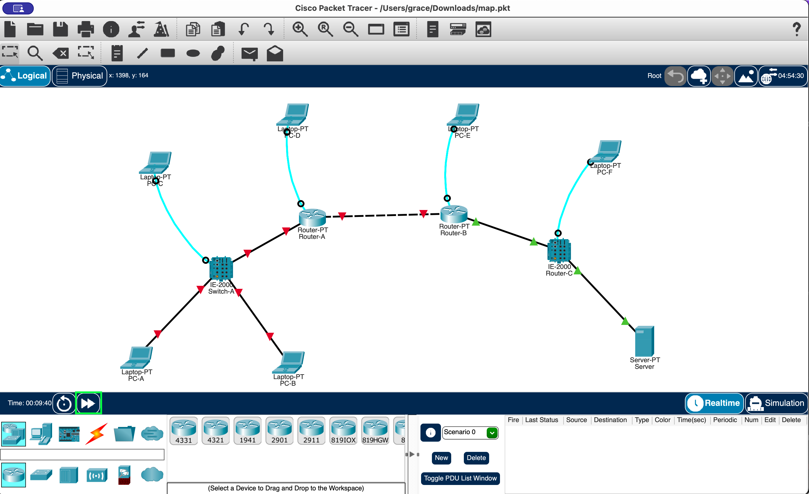 We can see that the link between router A and B, the link between router A and Switch A, and the access ports on Switch A all appear to be down.
To quickly see what port each device and cable is connected to:
- Go to Preferences
- Check
Always Show Port Labels in Logical Workspace.
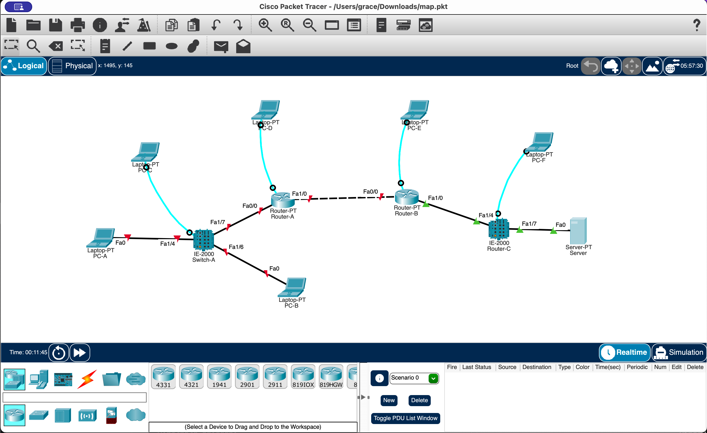 If the labels get in the way you can drag the devices around to move them.
What can we do?
Let’s quickly have a look at what options are available in the challenge environment before we continue.
When we connect we are greeted with a device selection menu:
❯ nc example.com 1234
Welcome to Network Troubleshooting Simulation!
Type '?' or 'help' for available commands

Available devices:
1. PCA
2. PCB
3. PCC
4. PCD
5. PCE
6. PCF
7. Exit

Select device (1-7):
If we select a PC that is connected via ethernet we will get a basic command prompt, similar to the Packet Tracer command prompt:
Select device (1-7): 1
1

PCA> ?
?

Available commands:
  ping <ip>
  ftp <ip>
  ipconfig
  ipconfig <ip> <mask> <gateway>
  traceroute <ip>
  arp -a
  cat <filename>
  netstat
  nslookup
  dir
  exit

PCA> exit
If we select a PC that has a console connection (e.g. PC C is connected to Switch A) we will get CLI access to the relevant router/switch:
Select device (1-7): 3
3
switchA> ?
?

Available commands:
  enable (en)
  exit
switchA> exit
Checking available commands on the device selection screen just brings up the device selection screen again.
We can’t add ethernet connections to PC E or PC F.
We’ll need to fix the links that are down and any problems between PC A/B and the server.
Packet Tracer - Getting more information
Server
Since we want to access the FTP server we need to know a little bit more about it.
If we click the Server, go the services tab, and click on FTP, we will see there is a file named flag.txt and a secret user with the password donttellanyone.
We also need the IP address information of the server, click the Desktop Tab to access the Command Prompt:
Cisco Packet Tracer SERVER Command Line 1.0
C:\>ipconfig

FastEthernet0 Connection:(default port)

Connection-specific DNS Suffix..:
Link-local IPv6 Address.........: FE80::206:2AFF:FE56:EAA3
IPv6 Address....................: ::
IPv4 Address....................: 192.168.1.5
Subnet Mask.....................: 255.255.255.0
Default Gateway.................: ::
                                  192.168.1.10
We can see it has the IP address 192.168.1.5/24 and the gateway 192.168.1.10.
While we’re here lets have a look at flag.txt:
C:\>ftp 192.168.1.5
Trying to connect...192.168.1.5
Connected to 192.168.1.5
220- Welcome to PT Ftp server
Username:secret
331- Username ok, need password
Password: donttellanyone
230- Logged in
(passive mode On)
ftp>get flag.txt

Reading file flag.txt from 192.168.1.5:
File transfer in progress...

[Transfer complete - 16 bytes]

16 bytes copied in 0 secs
ftp>quit

221- Service closing control connection.
C:\>
The Text Editor in the Desktop tab lets us view the file, it just says apoorvctf{hello}.
This is just an example flag so we can test accessing the FTP server inside packet tracer.
Addressing and Port Status
We’ll go from right to left to make sure everything’s working.
The server seems to be configured properly, so let’s move on to Router B.
Router B
Router B is connected to the server via a switch on Fa1/0.
Clicking Router B -> Config -> Fa1/0 we see the IP address 192.168.1.10/24 and the Port Status is On, this matches the default gateway the server had set so it should be correct.
The connection to router A is on Fa0/0, it doesn’t have an IP address yet and the Port Status is Off.
We don’t have the information we need to configure Fa0/0 yet - maybe Router A can tell us something useful?
Click Router A -> CLI to bring up the Cisco IOS CLI:
The
enablecommand is used to turn on privileged commands, like viewing configuration information.
(This is Router A)
Router>enable
Router#show ip interface brief
Interface IP-Address OK? Method Status Protocol
FastEthernet0/0 unassigned YES manual administratively down down
FastEthernet1/0 10.45.23.23 YES manual administratively down down
Serial2/0 unassigned YES unset administratively down down
Serial3/0 unassigned YES unset administratively down down
FastEthernet4/0 unassigned YES unset administratively down down
FastEthernet5/0 unassigned YES unset administratively down down
We can see the link from Router A to B has an address but we don’t know the subnet mask yet, we can get it with:
(This is Router A)
Router#show ip interface FastEthernet1/0
FastEthernet1/0 is administratively down, line protocol is down (disabled)
  Internet address is 10.45.23.23/8
Great, but what should Router B be? Let’s look at the full configuration:
(This is Router A)
Router#show running-config
[etc]
ip route 192.168.1.0 255.255.255.0 10.45.23.22
[etc]
We can see router A has a static route to the 192.168.1.0/24 network via 10.45.23.22.
We’ve seen that network connected to router B - 10.45.23.22 is the address we should give router B.
Summary:
- Router B should get
10.45.23.22/8onFa0/0and the interface should be bought up. - Fa1/0 was already configured and matched what we learned from the server.
Router A
Earlier we saw that router A only had an address on Fa1/0 - the link to router B.
The link was also administratively down.
We still need to configure Fa0/0 but don’t have enough information yet.
Maybe the PCs on its network can tell us more?
PC A:
C:\>ipconfig

FastEthernet0 Connection:(default port)
Connection-specific DNS Suffix..:
Link-local IPv6 Address.........: FE80::201:64FF:FEEB:1B8E
IPv6 Address....................: ::
IPv4 Address....................: 178.34.23.9
Subnet Mask.....................: 255.255.0.0
Default Gateway.................: ::
                                  0.0.0.0
PC B:
C:\>ipconfig

FastEthernet0 Connection:(default port)
Connection-specific DNS Suffix..:
Link-local IPv6 Address.........: FE80::2D0:58FF:FE23:B1E2
IPv6 Address....................: ::
IPv4 Address....................: 0.0.0.0
Subnet Mask.....................: 0.0.0.0
Default Gateway.................: ::
                                  0.0.0.0
Both PC’s had their ethernet interfaces on.
Neither of them seem to have a default gateway configured.
But if we check PC B’s Config tab, there is a default gateway of 142.72.23.3 under settings!
While PC A did have an IP address configured, that doesn’t mean it was correct.
Let’s quickly check what Router B expects this network to be:
RouterB>en
RouterB#show running
Building configuration...
[...]
ip route 142.72.23.0 255.255.255.0 10.45.23.23
[...]
We’ll need to change that one on PC A!
Summary:
- Router A should get IP
142.72.23.3/24onFa0/0which should also be turned on. Fa1/0should be turned on.
We have enough information to configure the routers and PC A/B.
The PCs ethernet ports are up, so why are the connections to switch A down?
Switch A
Let’s look at the port status on switch A:
Switch>enable
Switch#show interfaces status
Port Name Status Vlan Duplex Speed Type
Fa1/1 notconnect 1 auto auto 10/100BaseTX
Fa1/2 notconnect 1 auto auto 10/100BaseTX
Fa1/3 notconnect 1 auto auto 10/100BaseTX
Fa1/4 disabled 1 auto auto 10/100BaseTX
Fa1/5 notconnect 1 auto auto 10/100BaseTX
Fa1/6 disabled 1 auto auto 10/100BaseTX
Fa1/7 notconnect 1 auto auto 10/100BaseTX
Fa1/8 notconnect 1 auto auto 10/100BaseTX
Gig1/1 notconnect 1 auto auto 10/100BaseTX
Gig1/2 notconnect 1 auto auto 10/100BaseTX
Fa1/4 and Fa1/6 are disabled.
In the visual workspace we see these are the ones PC A/B are connected to, we’ll need to re-enable them.Fa1/7 is connected to the router but isn’t disabled, it should start working once Fa0/0 is up on Router A.
Summary of information
FTP Server:
- The FTP server has the IP address
192.168.1.5/24, with default gateway192.168.1.10 - The FTP server has two users
cisco:ciscosecret:donttellanyone
- It has a
flag.txtfile we’re interested in! - On the logical workspace its interfaces are up and working.
Router B:
- The interface connected to the server
Fa1/0has the IP address192.168.1.10/24and is on - this matches the configuration the FTP server expects. - The interface connected to Router A
Fa0/0needs to get the IP address10.45.23.22/8and needs to be turned on. - There is a static route to
142.72.23.0/24via10.45.23.23(Router A).
Router A:
- The interface connected to router B
Fa1/0has the IP address10.45.23.23/8and needs to be turned on. - The interface connected to PC A/B
Fa0/0needs to get the IP address142.72.23.3/24and needs to be turned on. - There is a static route to
192.168.1.0/24via10.45.23.22(Router B).
Switch A:
- Port Fa1/4 connected to PC A and Port Fa1/6 connected to PC B are both set to be down, at least one needs to be turned on.
PC A/B:
- We should configure either (or both) PC A/B with an IP address in the 142.72.23.0/24 network (other than
.3) with a default gateway of142.72.23.3. - We should use one of these PC’s to connect to the FTP server, download the flag.txt file and read it.
Solving in Packet Tracer
Now that we know what we need to do let’s try doing it in Packet Tracer first!
Re-open the map.pkt file without saving to make sure everything is as expected.
Fast-forward in the bottom left so interfaces and services come up quickly.
Now we can start :)
Router B
We’ll use PC E’s Terminal to access the CLI of Router B, since that’s what we’ll be doing in the challenge.
PC E -> Desktop -> Terminal.
- ⭐️ On router B we need to give
Fa0/0the IP address10.45.23.22/8and turn the interface on.
The
no shutdowncommand removesshutdownfrom the interfaces configuration, which turns it back on.
Router>enable
Router#configure terminal
Enter configuration commands, one per line. End with CNTL/Z.
Router(config)#interface fa0/0
Router(config-if)#ip address 10.45.23.22 255.0.0.0
Router(config-if)#no shutdown

Router(config-if)#
%LINK-5-CHANGED: Interface FastEthernet0/0, changed state to up
Router A
Now we can use PC D to configure router A.
- ⭐️ On router A we need to turn on interface
Fa1/0, we can ping router B on 10.45.23.22 to verify it worked.
Router>enable
Router#configure terminal
Enter configuration commands, one per line. End with CNTL/Z.
Router(config)#interface fa1/0
Router(config-if)#no shutdown

Router(config-if)#
%LINK-5-CHANGED: Interface FastEthernet1/0, changed state to up

%LINEPROTO-5-UPDOWN: Line protocol on Interface FastEthernet1/0, changed state to up

Router(config-if)#do ping 10.45.23.22

Type escape sequence to abort.
Sending 5, 100-byte ICMP Echos to 10.45.23.22, timeout is 2 seconds:
.!!!!
Success rate is 80 percent (4/5), round-trip min/avg/max = 0/0/0 ms
We can now ping router B from router A, there should be green indicators on the visual workspace as well!
dolets us run commands in privileged exec mode, as some commands don’t work from configure mode.⭐️
- ⭐️ On router A we need to configure
Fa0/0to have the IP address142.72.23.3/24and turn it on.
Router(config-if)#interface fa0/0
Router(config-if)#ip address 142.72.23.3 255.255.255.0
Router(config-if)#no shutdown

Router(config-if)#
%LINK-5-CHANGED: Interface FastEthernet0/0, changed state to up

%LINEPROTO-5-UPDOWN: Line protocol on Interface FastEthernet0/0, changed state to up
Switch A
We can configure Switch A from PC C, for the challenge we’ll just enable Fa1/4 which is connected to PC A.
Switch>enable
Switch#configure terminal
Enter configuration commands, one per line. End with CNTL/Z.
Switch(config)#interface fa1/4
Switch(config-if)#no shutdown

Switch(config-if)#
%LINK-5-CHANGED: Interface FastEthernet1/4, changed state to up

%LINEPROTO-5-UPDOWN: Line protocol on Interface FastEthernet1/4, changed state to up
In the visual workspace all links from PC A to the server should have green indicators!
PC A
We can configure PC A from the command prompt under its Desktop tab.
PC A needs an IP address in the 142.72.23.0/24 network (other than .3) and a default gateway of 142.72.23.3.
In Packet Tracer ipconfig lets you set an IP address and gateway:
C:\>ipconfig /?
Cisco Packet Tracer PC IP Configuration

Usage:
ipconfig { /? | /renew | /release | <IP> <subnet mask> [<default gateway>] }

C:\>ipconfig 142.72.23.20 255.255.255.0 142.72.23.3
C:\>ipconfig

FastEthernet0 Connection:(default port)

   Connection-specific DNS Suffix..:
   Link-local IPv6 Address.........: FE80::201:64FF:FEEB:1B8E
   IPv6 Address....................: ::
   IPv4 Address....................: 142.72.23.20
   Subnet Mask.....................: 255.255.255.0
   Default Gateway.................: ::
                                     142.72.23.3
We should also verify we can ping the default gateway and the server:
C:\>ping 142.72.23.3

Pinging 142.72.23.3 with 32 bytes of data:

Reply from 142.72.23.3: bytes=32 time=1ms TTL=255
Reply from 142.72.23.3: bytes=32 time=20ms TTL=255
Reply from 142.72.23.3: bytes=32 time=2ms TTL=255
Reply from 142.72.23.3: bytes=32 time=57ms TTL=255

Ping statistics for 142.72.23.3:
    Packets: Sent = 4, Received = 4, Lost = 0 (0% loss),
Approximate round trip times in milli-seconds:
    Minimum = 1ms, Maximum = 57ms, Average = 20ms

C:\>ping 192.168.1.5

Pinging 192.168.1.5 with 32 bytes of data:

Request timed out.
Reply from 192.168.1.5: bytes=32 time<1ms TTL=126
Reply from 192.168.1.5: bytes=32 time=28ms TTL=126
Reply from 192.168.1.5: bytes=32 time=31ms TTL=126

Ping statistics for 192.168.1.5:
    Packets: Sent = 4, Received = 3, Lost = 1 (25% loss),
Approximate round trip times in milli-seconds:
    Minimum = 0ms, Maximum = 31ms, Average = 19ms

C:\>
Now let’s get the demo flag.txt to verify that works correctly:
C:\>ftp 192.168.1.5
Trying to connect...192.168.1.5
Connected to 192.168.1.5
220- Welcome to PT Ftp server
Username:secret
331- Username ok, need password
Password:
230- Logged in
(passive mode On)
ftp>get flag.txt

Reading file flag.txt from 192.168.1.5:
File transfer in progress...

[Transfer complete - 16 bytes]

16 bytes copied in 0 secs
ftp>quit

221- Service closing control connection.
C:\>
Viewing it in the text editor of PC A we see apoorvctf{hello}!
Commands Summary
Before we go ahead and do it in the challenge lets make a list of the commands we used for quick reference.
PC-E -> Router B:
enable
configure terminal
interface fa0/0
ip address 10.45.23.22 255.0.0.0
no shutdown
PC-D -> Router A:
enable
configure terminal
interface fa1/0
no shutdown

ping 10.45.23.22

interface fa0/0
ip address 142.72.23.3 255.255.255.0
no shutdown
PC-C -> Switch A:
enable
configure terminal
interface fa1/4
no shutdown
PC-A:
ipconfig 142.72.23.20 255.255.255.0 142.72.23.3
ping 142.72.23.3
ping 192.168.1.5
ftp 192.168.1.5
(login secret:donttellanyone)
get flag.txt
quit
Solving in Challenge Environment
Routers and Switches
PC-E -> Router B:
Available devices:
1. PCA
2. PCB
3. PCC
4. PCD
5. PCE
6. PCF
7. Exit

Select device (1-7): 5
5

routerB> enable
enable

routerB# configure terminal
configure terminal

routerB(config)# interface fa0/0
interface fa0/0

routerB(config-if-fa0/0)# ip address 10.45.23.22 255.0.0.0
ip address 10.45.23.22 255.0.0.0
IP address configured for fa0/0

routerB(config-if-fa0/0)# no shutdown
no shutdown
Interface fa0/0 enabled

routerB(config-if-fa0/0)# exit
exit

routerB(config)# exit
exit

routerB# exit
exit

routerB> exit
PC-D -> Router A:
Available devices:
1. PCA
2. PCB
3. PCC
4. PCD
5. PCE
6. PCF
7. Exit

Select device (1-7): 4
4

routerA> enable
enable

routerA# configure terminal
configure terminal

routerA(config)# interface fa1/0
interface fa1/0

routerA(config-if-fa1/0)# no shutdown
no shutdown
Interface fa1/0 enabled

routerA(config-if-fa1/0)# exit
exit

routerA(config)# exit
exit

routerA# ping 10.45.23.22
ping 10.45.23.22
Invalid command

routerA# configure terminal
configure terminal

routerA(config)# interface fa0/0
interface fa0/0

routerA(config-if-fa0/0)# ip address 142.72.23.3 255.255.255.0
ip address 142.72.23.3 255.255.255.0
IP address configured for fa0/0

routerA(config-if-fa0/0)# no shutdown
no shutdown
Interface fa0/0 enabled

routerA(config-if-fa0/0)# exit
exit

routerA(config)# exit
exit

routerA# exit
exit

routerA> exit
We tried to ping to verify but ping is not available here.
PC-C -> Switch A:
Available devices:
1. PCA
2. PCB
3. PCC
4. PCD
5. PCE
6. PCF
7. Exit

Select device (1-7): 3
3
switchA> enable
enable
switchA# configure terminal
configure terminal
switchA(config)# interface fa1/4
interface fa1/4
switchA(config-if-fa1/4)# no shutdown
no shutdown
Interface fa1/4 enabled
switchA(config-if-fa1/4)# exit
exit
switchA(config)# exit
exit
switchA# exit
exit
switchA> exit
PC-A
Available devices:
1. PCA
2. PCB
3. PCC
4. PCD
5. PCE
6. PCF
7. Exit

Select device (1-7): 1
1

PCA> ipconfig 142.72.23.20 255.255.255.0 142.72.23.3
ipconfig 142.72.23.20 255.255.255.0 142.72.23.3
IP configuration updated successfully

PCA> ping 142.72.23.3
ping 142.72.23.3

Pinging 142.72.23.3 with 32 bytes of data:
Reply from 142.72.23.3: bytes=32 time=1ms TTL=64
Reply from 142.72.23.3: bytes=32 time=1ms TTL=64
Reply from 142.72.23.3: bytes=32 time=1ms TTL=64
Reply from 142.72.23.3: bytes=32 time=1ms TTL=64

Ping statistics for 142.72.23.3:
    Packets: Sent = 4, Received = 4, Lost = 0 (0% loss)
Approximate round trip times in milli-seconds:
    Minimum = 1ms, Maximum = 1ms, Average = 1ms

PCA> ping 192.168.1.5
ping 192.168.1.5

Pinging 192.168.1.5 with 32 bytes of data:
Request timed out.
Request timed out.
Request timed out.
Request timed out.

Ping statistics for 192.168.1.5:
    Packets: Sent = 4, Received = 0, Lost = 4 (100% loss)

PCA>
🚨 We’ve configured PC-A but can’t ping the server, what’s up with that?
Let’s check the running-config of one of the routers.
PC-D -> Router A:
Available devices:
1. PCA
2. PCB
3. PCC
4. PCD
5. PCE
6. PCF
7. Exit

Select device (1-7): 4
4

routerA> enable
enable

routerA# show running-config
show running-config
Command coming soon...

routerA#
Can’t do that!
Let’s try adding the static routes on both routers in case that’s the problem.
PC-D -> Router A:
routerA# configure terminal
configure terminal

routerA(config)# ip route 192.168.1.0 255.255.255.0 10.45.23.22
ip route 192.168.1.0 255.255.255.0 10.45.23.22
Route added

routerA(config)#
And PC-E -> Router B:
Select device (1-7): 5
5

routerB> enable
enable

routerB# configure terminal
configure terminal

routerB(config)# ip route 142.72.23.0 255.255.255.0 10.45.23.23
ip route 142.72.23.0 255.255.255.0 10.45.23.23
Route added

routerB(config)#
Flag 🚩
Everything should be configured properly now.
Let’s go back to PC-A and see if we can reach the server!
PCA> ping 192.168.1.5
ping 192.168.1.5

Pinging 192.168.1.5 with 32 bytes of data:
Reply from 192.168.1.5: bytes=32 time=1ms TTL=64
Reply from 192.168.1.5: bytes=32 time=1ms TTL=64
Reply from 192.168.1.5: bytes=32 time=1ms TTL=64
Reply from 192.168.1.5: bytes=32 time=1ms TTL=64

Ping statistics for 192.168.1.5:
    Packets: Sent = 4, Received = 4, Lost = 0 (0% loss)
Approximate round trip times in milli-seconds:
    Minimum = 1ms, Maximum = 1ms, Average = 1ms

PCA>
Great, let’s download the flag and look at it! 🚩
PCA> ftp 192.168.1.5
ftp 192.168.1.5
Connected to 192.168.1.5
220 FTP server ready
Name: secret
secret
Password: donttellanyone
donttellanyone
230 Login successful
ftp> get flag.txt
get flag.txt
200 PORT command successful
150 Opening BINARY mode data connection for flag.txt
226 Transfer complete
Downloaded flag.txt
ftp> quit
quit
221 Goodbye.

PCA> cat flag.txt
cat flag.txt
apoorvctf{this_is_not_the_actual_flag}

PCA>